|
Experiment # 4 August 2006 |
EE 201P
Digital Electronics Laboratory II
| HOME | EXPERIMENTS | SCHEDULE | USEFUL LINKS | LAB QUIZZES | GRADES |
|
(a) Implementation of following flip flops using NAND gates
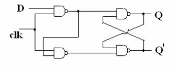
(i) D flip flop using minimum hard ware
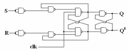
(ii) Edge triggered S-R flip flop
(b) Implementation of following flip flop using D flip flop
(i) S-R flip flop
(ii) JK flip flop
(iii) T flip flop
The required circuit(s) should be implemented as per problem statement using TTL ICs familiarized in previous experiments.All the product datasheets (pin diagrams) are available online and should be used to construct the circuit diagram. The LEDs and resistances (if required) can be used to display the logic output.
III. Experimental Procedure
Part A
1. Realize the following circuit using only NAND gates. Please select appropriate ICs and LEDs for the display.
2. Construct the truth table of above circuit and identify the problems faced by this configuration.
3. Realize the following circuit using only NAND gates. Please select appropriate ICs and LEDs for the display.
4. Construct the truth table of above circuit and identify the problems faced by this configuration.
Part B
1. Design S-R flip flop, ,J-K flip flop and T flip flop using a D flip flop and additional logic gates .
2.Verify the truth table for each of the above circuits.
3. Compare the obtained truth tables with the actual truth tables.
IV. Other Pre-Lab Exercises
1. Consider a flip flop circuit as shown in the following figure.

(a) Obtain the flip-flop characteristic table.
(b) Obtain the characteristic equation.
(c) Derive its excitation table.
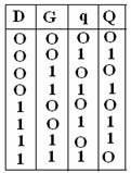
2. Design a D-G flip flop, where D and G are flip flop the inputs 'q' is the present state, and Q is the next state of flip flop. The truth table of this flip flop is shown below.
3. Q out put of a positive edge triggered S-R flip flop is shown below. Determine its inputs S and R.

Please make sure that you have shown the result of your implementation to the lab instructor (or TA) and obtained his/her signature. The two partner's in each group must obtain the signatures and attach with the lab/experiment report.