|
Experiment # 3 August 2006 |
EE 201P
Digital Electronics Laboratory II
| HOME | EXPERIMENTS | SCHEDULE | USEFUL LINKS | LAB QUIZZES | GRADES |
|
(a) Construct a truth table for the following two Boolean circuits shown below.
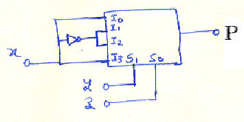

(b) Determine the function performed by this circuit at its output P and Q.
(c) Realize the following function using (i) 8 to 1 Multiplexer and (ii) 4 to 1 Multiplexers with minimum of additional gates.
F = S (0, 1, 3, 6, 7, 8, 11, 12, 14)
Part (a) and (b)
74153 1
Resistance (330 W) 2
LEDs 2
Part (c)
74153 1
74151 1
Resistance (330 W) 2
LEDs 2
and additional logic gates (only if required)
III. Experimental Procedure
(a) Make the connection for the above given circuit using . Please use pin diagram for the corresponding ICs to locate the required gates. Connect all Vcc pins to 5V.
(b) Connect the given LEDs to the output P/Q. Make sure that you use given resistor to limit the current in LED.
(c) Apply all the possible combination of binary inputs to the x, y and z terminals. Construct the truth table for the circuit.
(d) Use the truth table to evaluate the logic function realized by the circuit.
(e) Identify the function executed by this circuit.
(f) Realize the given functions using (i) 8 to 1 and (ii) 4 to 1 Multiplexers separately.